

- Geopro Jetting Shoe (GJS178) GEN3.0
- Centralizers GeoGLIDER Xtreme Lite GGXL178
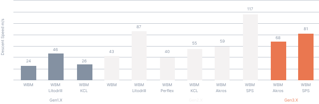
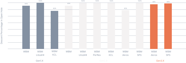
- CRT descent system

1620-1910 m
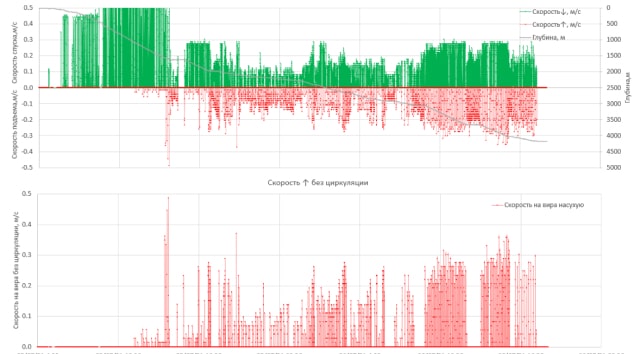
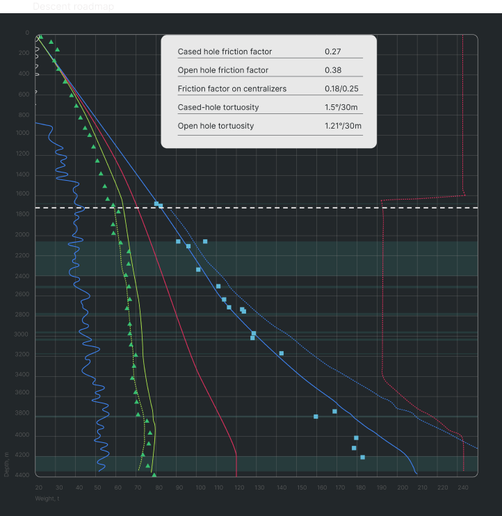
- 1620 m: washing and tracing dry, the friction factor was specified and cased hole tortuosity: 0.27 and 1.5 ° / 30 m.
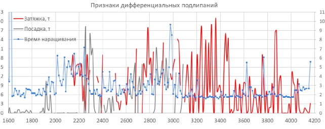
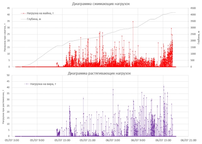
- 1830-1850 m: openhole subsequent run continued dry, landings of up to 7 tons were received, shoot down without circulation.
- 1910 m: a landing was met when the column was disrupted after a build-up of 9 tons.
- 1980 m: after 2 consecutive landings of 15 tons, circulation starts, flushing performs in the volume of the annulus.

2120-2280 m
- 1620 m: washing and tracing dry, the friction factor was specified and cased hole tortuosity: 0.27 and 1.5 ° / 30 m.
- 1830-1850 m: openhole subsequent run continued dry, landings of up to 7 tons were received, shoot down without circulation.
- 1910 m: a landing was met when the column was disrupted after a build-up of 9 tons.
- 1980 m: after 2 consecutive landings of 15 tons, circulation starts, flushing performs in the volume of the annulus.

2280-2910 m
- 1620 m: washing and tracing dry, the friction factor was specified and cased hole tortuosity: 0.27 and 1.5 ° / 30 m.
- 1830-1850 m: openhole subsequent run continued dry, landings of up to 7 tons were received, shoot down without circulation.
- 1910 m: a landing was met when the column was disrupted after a build-up of 9 tons.
- 1980 m: after 2 consecutive landings of 15 tons, circulation starts, flushing performs in the volume of the annulus.

2910-3050 m
- 1620 m: washing and tracing dry, the friction factor was specified and cased hole tortuosity: 0.27 and 1.5 ° / 30 m.
- 1830-1850 m: openhole subsequent run continued dry, landings of up to 7 tons were received, shoot down without circulation.
- 1910 m: a landing was met when the column was disrupted after a build-up of 9 tons.
- 1980 m: after 2 consecutive landings of 15 tons, circulation starts, flushing performs in the volume of the annulus.
3050-4040 m
- 1620 m: washing and tracing dry, the friction factor was specified and cased hole tortuosity: 0.27 and 1.5 ° / 30 m.
- 1830-1850 m: openhole subsequent run continued dry, landings of up to 7 tons were received, shoot down without circulation.
- 1910 m: a landing was met when the column was disrupted after a build-up of 9 tons.
- 1980 m: after 2 consecutive landings of 15 tons, circulation starts, flushing performs in the volume of the annulus.